
The Smart Workshop is one of my main projects. It’s currently I am working on Version 2.0 but here you can find both of the Versions. Let’s begin with V1.0
Smart Workshop V1.0
Everything started with the Smart Workshop V1.0
The basic idea was a system that would automatically turn on the lights as soon as I entered my workshop. Additionally, a few relays were to be installed in case of additional ideas.
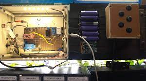
And so the construction began. The heart of the project was an Arduino Nano. This was accompanied by a motion sensor (PIR), 2 relays, a power supply, external switches, and a backup battery.
The motion sensor was supposed to detect when I was in the workshop and send a signal to the Arduino to turn on the lights. A second relay was to be manually switched through a switch on the control box.
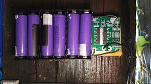
The backup battery consisted of 3 batteries connected in series, each with 6 parallel batteries, and was intended for use in the event of a power failure. It was supposed to supply both the control and the lighting with 12V, so that I could possibly finish projects.
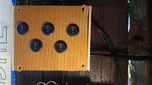
The control box was designed to allow for manual operation in case the automatic system failed, with these switches bypassing the relays.
The power supply consisted of a 230V to 12V power supply and a 7805 voltage regulator, which provided the system with the necessary voltages.
Below are pictures of the old system, however, many parts were reused in the construction of the V2.0, so the old system was dismantled.


Smart Workshop V2.0
Planing and goal setting
The development of the Smart Workshop V2.0 has begun. The most important goal for the second version: make it newer and better. My other goals for the project are:
— more organized, tidier PCB
— Mat black housing
— Addition of a 24V power supply
— more neatly looking Battery storage in a box with a plug for easier removal
Planing
To start, I made up some sort of plan. For that, I used plain old pen and paper. I first started wiring a wiring diagram and layout plan for the battery pack. After that, I started working on the Layout and wiring of the main PCB as well as my lighting panel.
While I started building everything, I noticed it would be fitting to switch the lighting. I thought of maybe making a separate fusebox for my stuff, so my devices are protected, the light is on a separate circuit, and maybe I can have two separately protected.
So I started working on a plan for that but more on that later.
Let the build begin
The build goes on
Because my old workshop was out in the open and exposed to the cold temperatures in the winter, I laid off work for some time until I could work outside again.
But then got offered the old Workshop of my Grandpa. I of course couldn’t say no to that, so I started moving all my stuff over.
I mounted the new control box, and the battery box, routed some new cables, and so on.
This allowed me to make a new, separate Power supply for the lighting. This included a 12V as well as a 24V Power supply for both the LED Strips, and the relays. I also added RGB lighting.
Alternations
While building the system I noticed, that using 24V instead of 12V would be inefficient, and so I redesigned the system to use 12V. 24V should only be kept as the Voltage for the Relays. Since Changing the System required changing the Battery, I’ve also changed the Cell configuration from 6S2P to 3S4P, meaning I halved the Voltage but doubled the capacity.
To be continued
As stated, the project is still under development and I am still working on it. I will still keep you updated.
See you soon